
Yamaha DX9 Synth Upcycle Repair
Upcycling an old Yamaha DX9 synth into a DX7 synth. Basically turning a 4-operator FM synth into a 6-operator synth. Also includes dome repairs on the way the should be applicable to the DX9 and DX7.
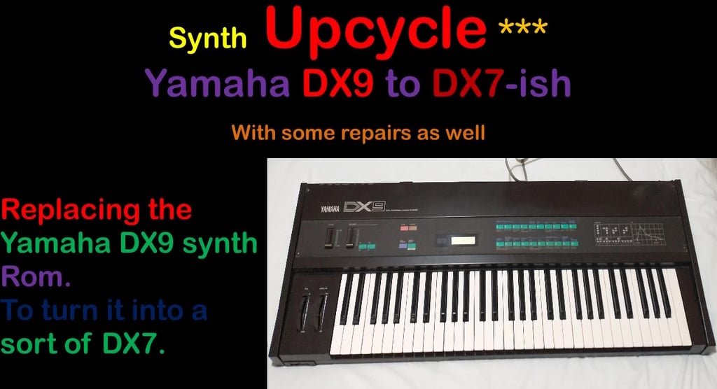
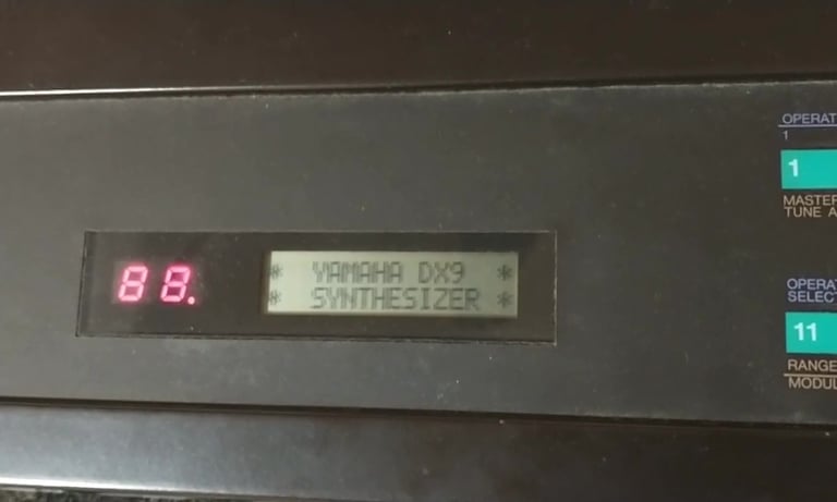
Turning my Yamaha DX9 synth into a DX7 (sort of) With some repairs on the way
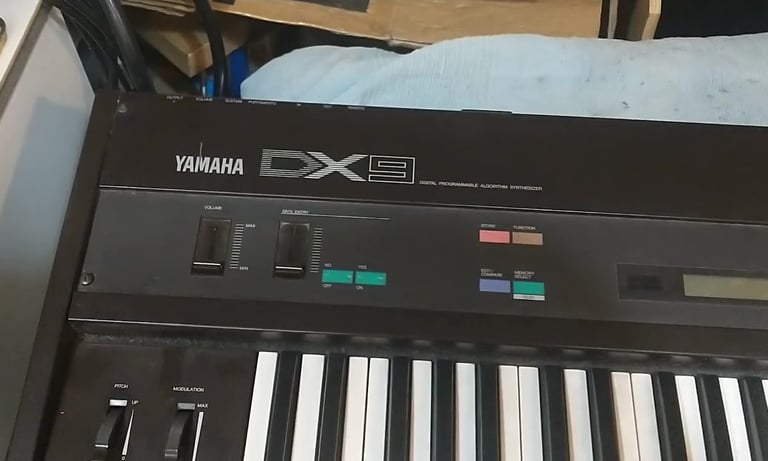
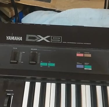
I had an old Yamaha DX9 synthesizer kicking about somewhere under the bed (the place to keep all keyboard synths ?) and it must have been there for over 10 years. Anyway, I recently decided I wanted to give FM synthesis a go again, so I thought I'd try and start the old synth up again.
So when I started to extract the synth from its incarceration, I thought that I would probably have to replace the RAM battery. I looked into how to do this and along the way I also found some interesting stuff about a new firmware ROM that had been developed for the DX9.
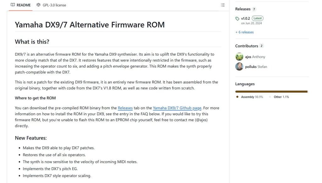
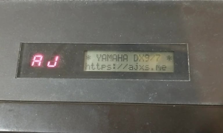
The new firmware ROM had been developed by AJXS here https://github.com/ajxs/yamaha_dx97 and basically turns a DX9 synth into a DX7 synth (as a lot of the hardware is the same). Right, you don't get the following.....
DX7 aftertouch from the DX9 synth keybed. (I use external keyboards anyway and that seems to work)
Ability to edit all 6 operators from the DX9 front panel. **
It Only allows 10 patches to be loaded onto the synth.......
And possibly other bits that are outlined in the readme on the site.
But it does allow you to upload DX7 patches to the Synth and it also allows you to edit them using an external PC based editor editor, such as Edisyn, which seems to work very well.
** Note: I'm considering programming an Arduino board as an add-on to allow me to edit parameters without having to use a PC.
What you will need to Program the New Eprom
So the following is a list of the special things you will need if you want to do the conversion.
Firmware ROM binary file. Downloadable from the previous link.
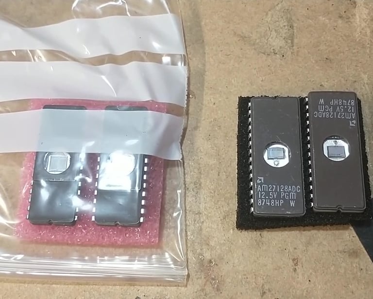
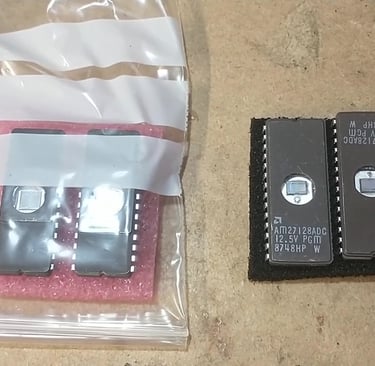
A 128k Eprom - A 27128 series 28-pin Eprom is required. Note: some synths have 2x 64k Eproms, so check first.
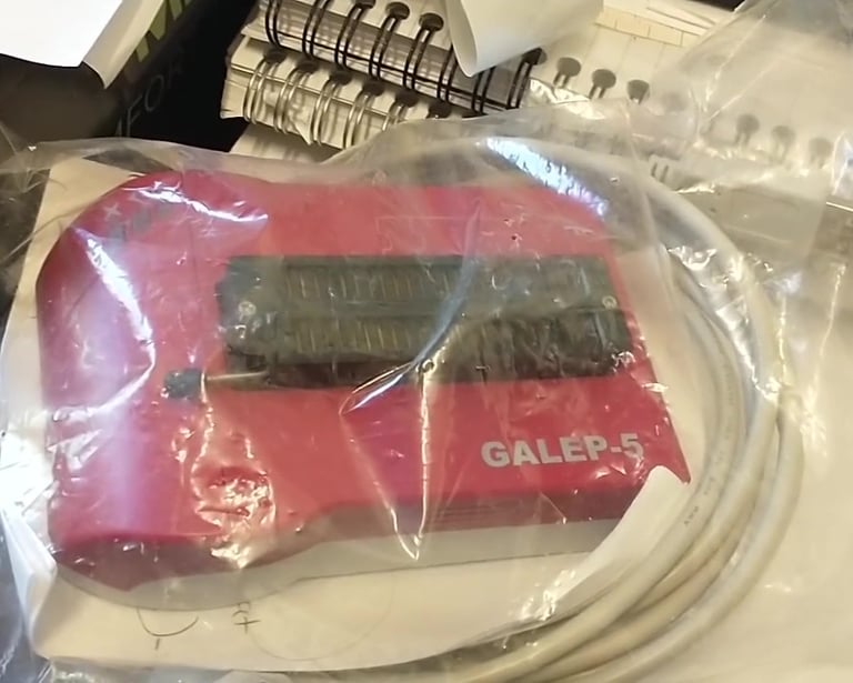
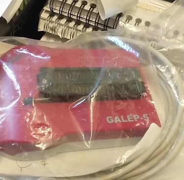
An Eprom programmer with the associtaed software - I used a Galep 5.
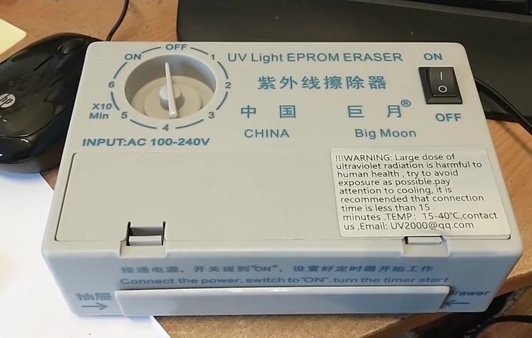
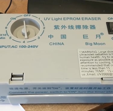
Possibly a UV Eprom eraser. Note: Most of the Eproms I bought second hand have already been erased. Ive only had to used the eraser on ones I pulled from old equipment.
First things first - Battery change
I expected that the battery would need changing, so I had a look at how to do it. Note, I knew how to remove the components on the board, but was more looking at the access, i.e. do you have to remove the back or front panels etc.
Note: Some of the tutorials mention that you have to remove the back panel of the synth, however I found that you just have to remove the front panel. The panel also conveniently hinges backwards.
So the process is as follows.....
1) Remove the four corner screws on top of the synth and one screw from the back right-hand corner of the synth.
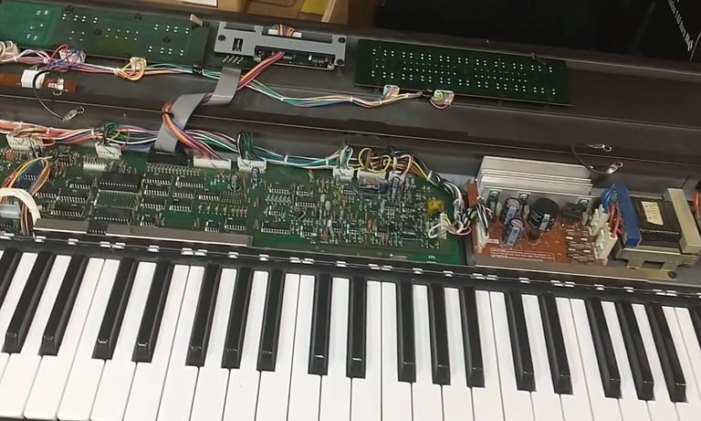
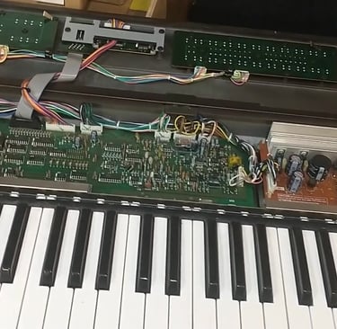
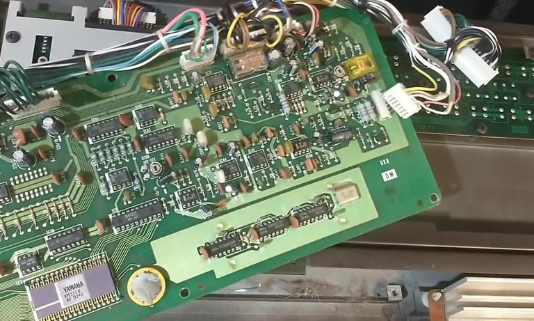
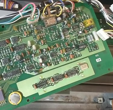
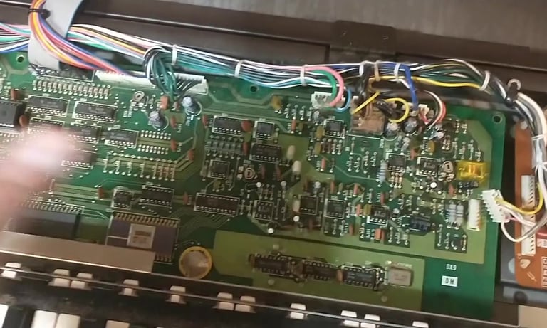
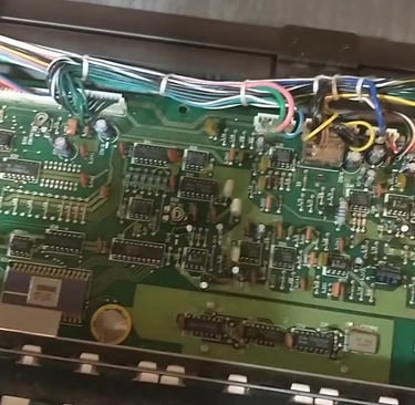
2) Carefully lift the cover up, it should hinge backwards. You should now see the synth boards.
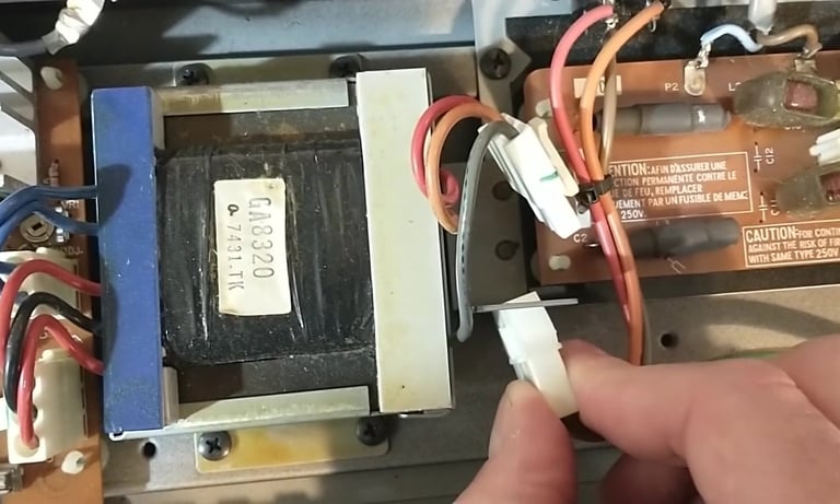
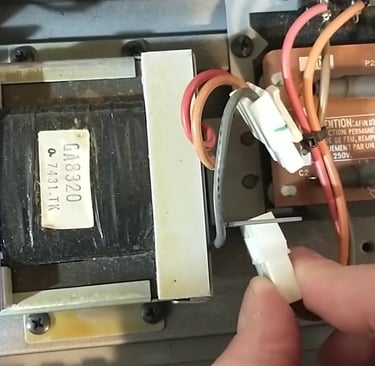
3) I disconnected the connector between the transformer and the PSU board (Be very careful when doing this as the capacitors could still have some charge MAKE SURE THE SYNTH IS UNPLUGGED)
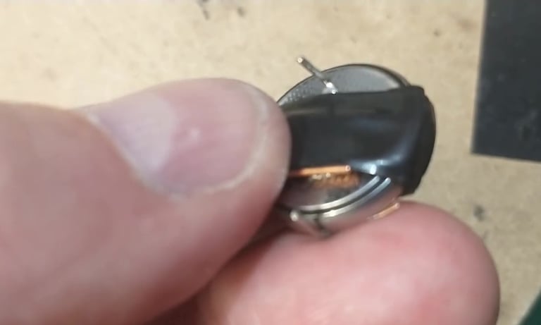
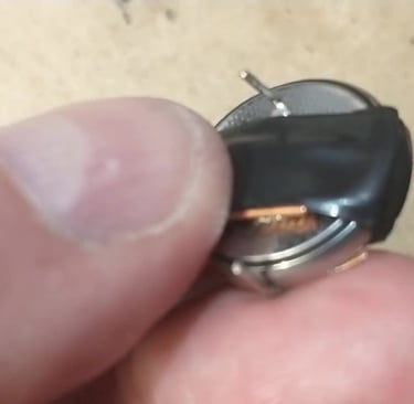
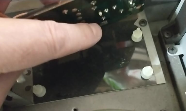
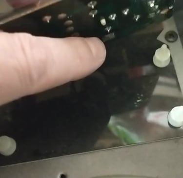
4) You should see the battery on the board (mine is pretty corroded).
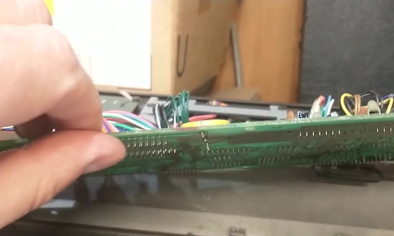
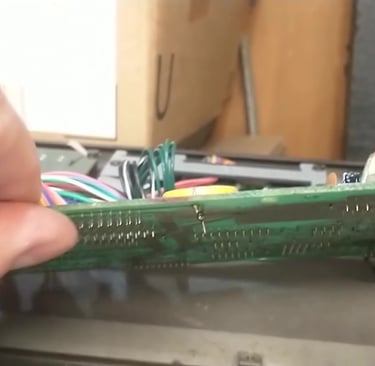
5) You need to remove the board with the battery on it: Note: I found that I only had to disconnect the right hand connectors on the board and carefully ease the cables at the back of the board from under the housing. This allowed me to manipulate the board and gain access to replace the battery.
6) The main board is fixed by eight screws at the edges of the board. Remove these and follow step 5.
7) Once all of the screws are removed you should be able to gently manoeuvre the board so you can gain access to the battery terminals.
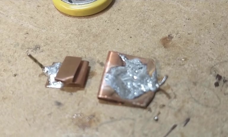
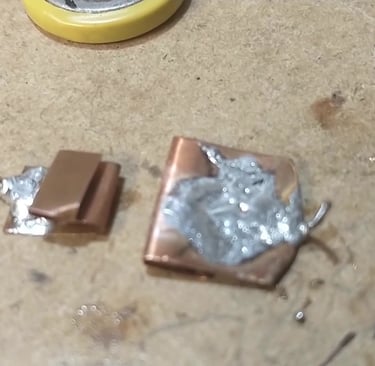
8) De-solder the battery. I found it best to apply some heat with a soldering iron to the nearest terminal, whilst gently levering the battery upwards with a screwdriver. This should free one terminal, then the battery can be pulled out whilst heating the other terminal. Note it is also possible to cut the terminals - remove the battery and then remove the terminal wires separately, however I wanted to keep the terminals in-tact.
9) Clean the holes on the board with solder wick and / or a solder sucker, then clean the board under the battery with IPA.
10) Note: This is an aside -skip if you have the correct replacement battery with attached terminals. I didn't have a correct battery with terminals as a replacement, but I did have a load of conventional un-terminated ones. That's why I wanted to keep the terminals in-tact in the last stage. I cut the terminals off of the old battery using a Stanley knife. I was going to solder these terminals to a new battery, but the battery I had was coated and couldn't be soldered (I have managed it in the past BUT I WOULDNT RECOMEND IT as batteries can explode if heated !) Should really spot weld them ... but I couldn't find my spot welder. Anyway, as I couldn't solder it, I made up some new contacts using the old terminals.
11) Refitting the battery and switch on should be the reverse of the above procedure. Just make sure that all of the cables are routed correctly before tightening any screws, closing lids, etc.
Oh No ! Magic Smoke
So, I replaced the battery and was then looking forward to doing the ROM upgrade, when a strange burning smell started coming from the synth. In addition the synth would turn on even if the switch on the back was off.
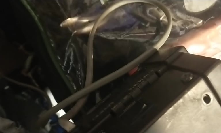
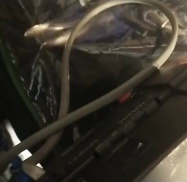
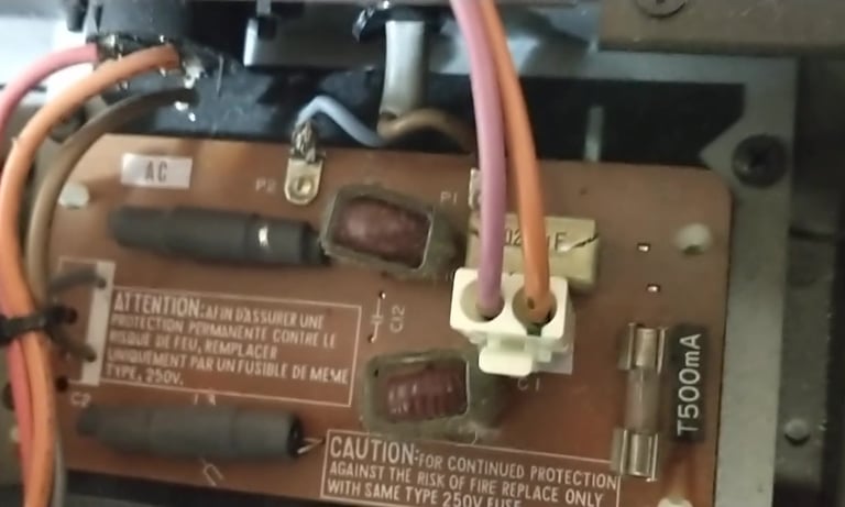
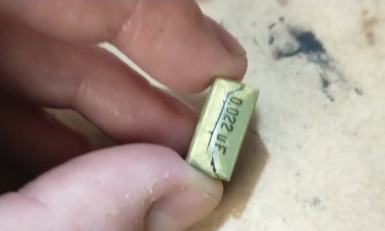
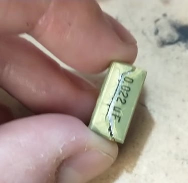
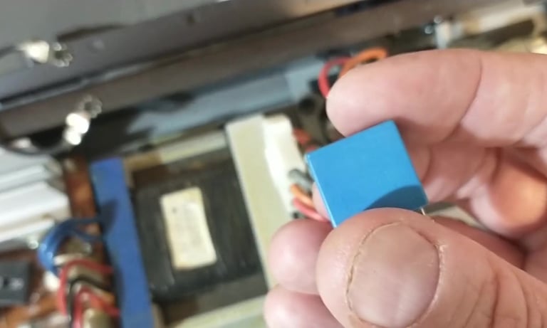
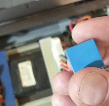
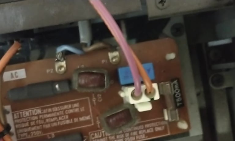
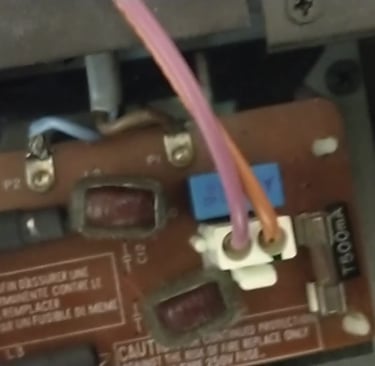
After a visual inspection I located a cracked capacitor on the mains inlet filter. Funnily enough this capacitor is placed across the switch, so wont do much when the switch is closed. The filter capacitors like this are usually Y2 rated (safety rated, that fail open) capacitors and they are placed across the supply rails. I'm pretty sure that the synth would work Ok without this capacitor, but I decided to replace it anyway, as I had some suitable capacitors spare.
Note: The original capacitor was a RIFA metalized paper capacitor..... these capacitors are notorious for failing over time (they can also absorb moisture which doesn't help)
I replaced the capacitor with a Metalized polyester one.
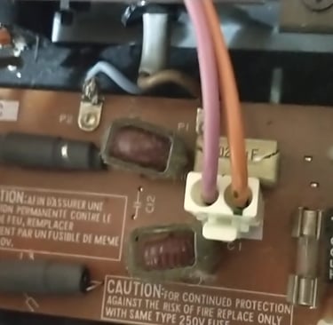
If the connectors are removed from the inlet filter, the board can be lifted without having to de-solder the other wires.
The board has four plastic retaining posts. If you squeeze these gently with pliers you should be able to work the board free.
You should then be able to de-solder the bad capacitor, and replace a new one with the board in-situ.
After I did this, there was no more burnt smell and the synth seemed to operate OK.
Note: when the synth was open I also checked the electrolytic capacitors on the power supply and they all seemed to be ok.
So now I could try and program, and fit the new ROM.
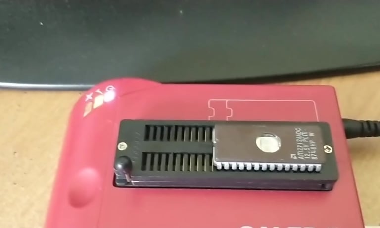
Finally Programming and Fitting the Eprom
So after doing all of the above I was ready to program a new Eprom. The process was carried out in the following way.
1) Obtain the Binary file (as explained at the start from the Github AJXS page there is a link on it).
2) Make sure you have the right Eproms.
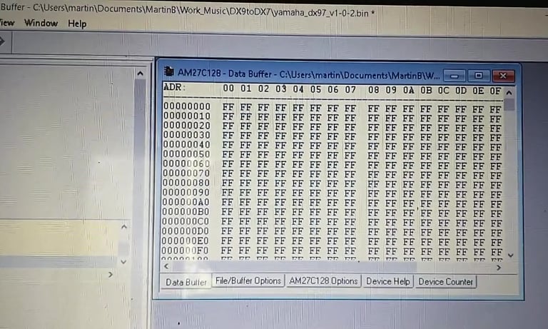
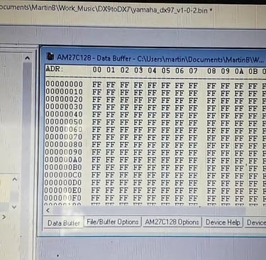
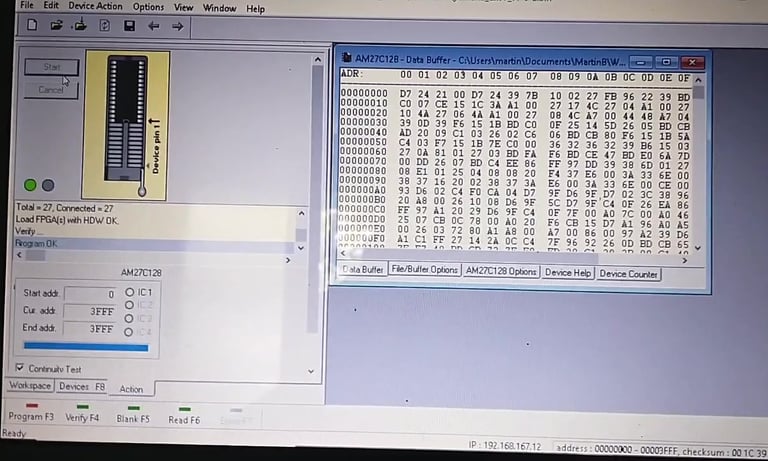
3) Set up the programmer and then verify that the device you want to program is blank. Usually a read operation should return All 0xFF in the memory location if it is a blank device (some software also has a 'blank check' option.
4) If it isn't blank then erase it.
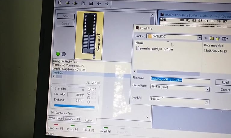
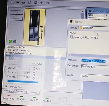
5) Load the binary file into your programming software.
6) Program and verify the device.
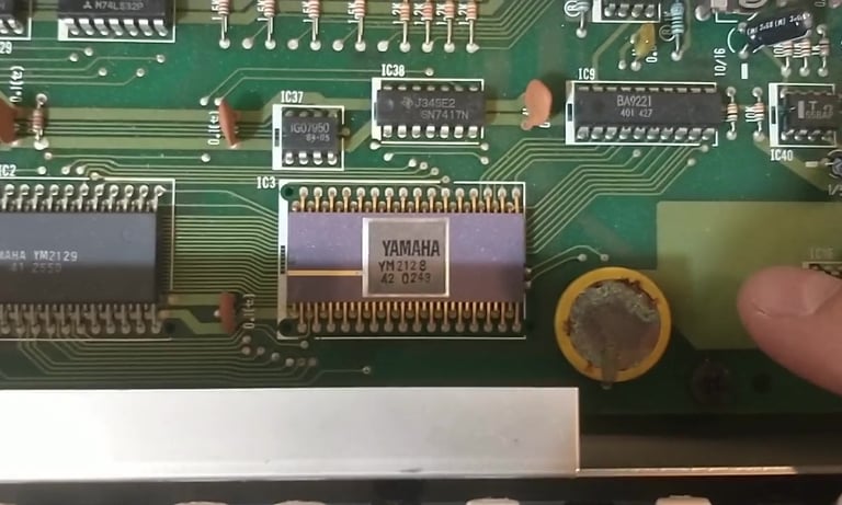
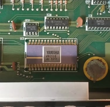
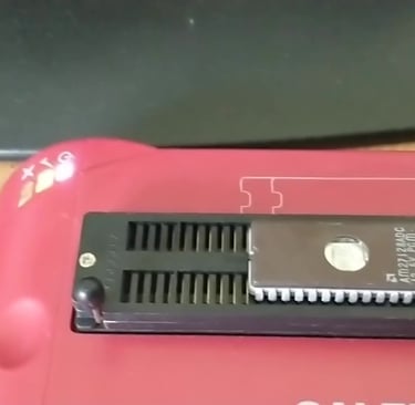
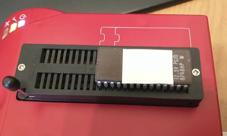
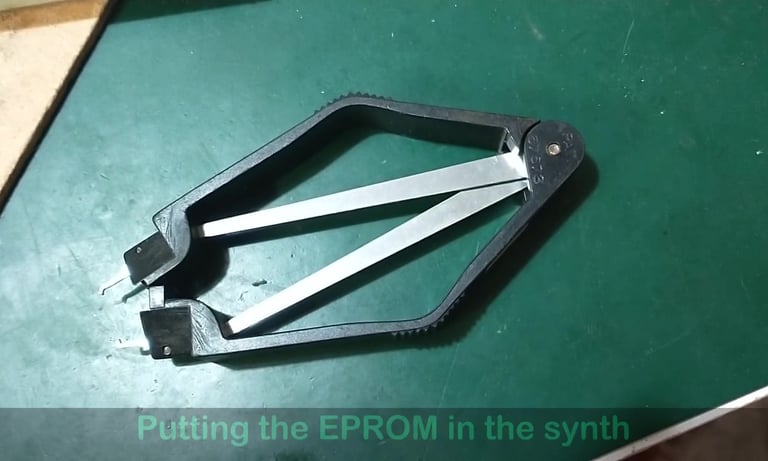
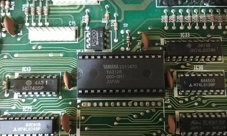
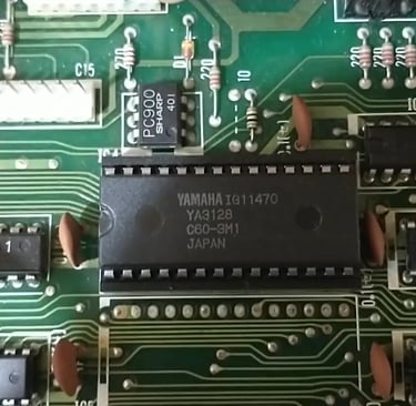
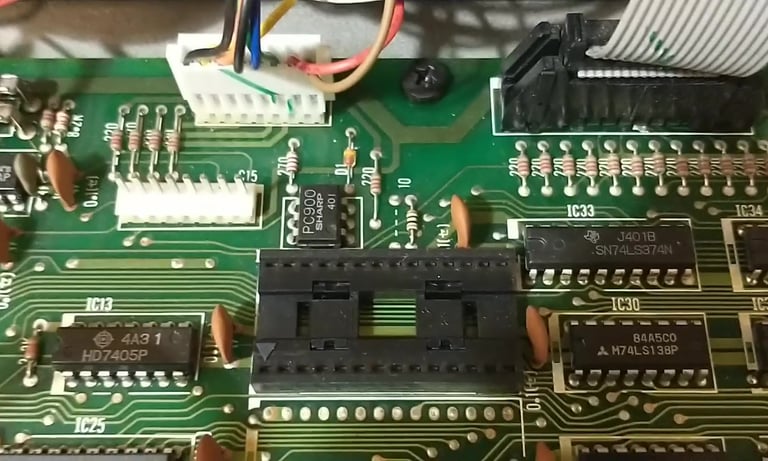
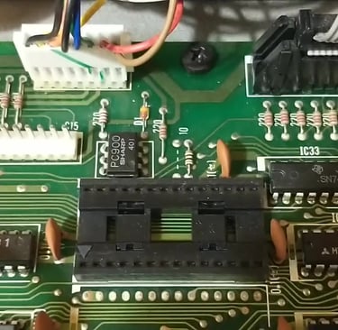
7) Carefully remove the original ROM from the synthesizer. Note be very careful here, as you don't want to bend any pins, just in case you want to re-use the ROM in the future. IC extractors are recommended.
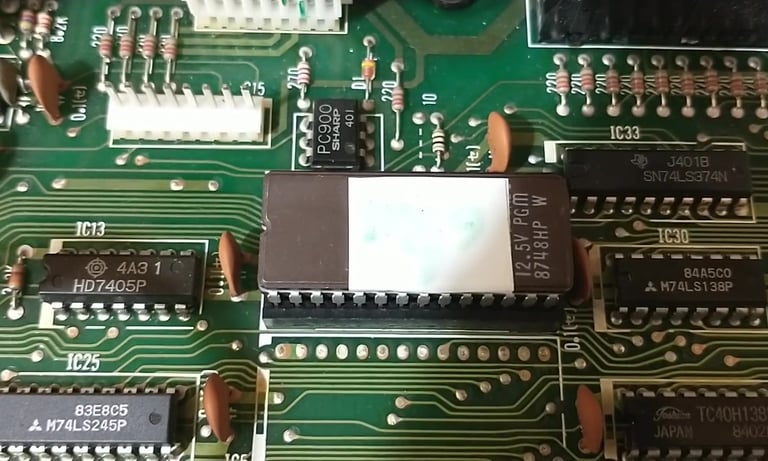
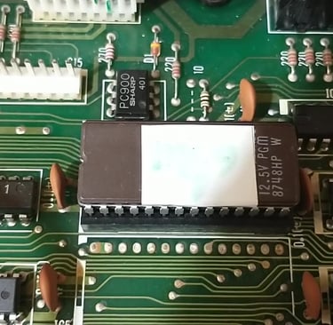
8) Insert the new Eprom into the socket. Make sure it is the right way round. Be careful not to bend any pins. You may have to gently try and form them to get them to go into the socket.
9) Put every thing together, power up the synth and hopefully it should now be a 6-operator DX7 sort of synth.
Final setting up
So after switching on the synth I tried to play some sounds, but all that came out was random garbage stuff (some bits sounded quite good as patches but I don't know how you would be able to save them). This was because the synth had not had any of the patches initialized.
Note: on the firmware upgrade page it mentions pressing the function button, as the synth boots up, to initialize it, but I couldn't get this to work.
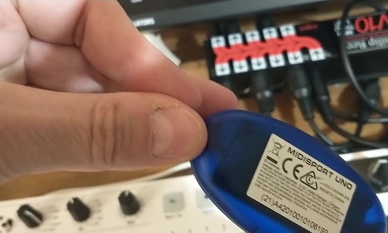
However, I managed to load new patches into the synth using sysex files, via a usb to midi cable. To do this you will need the following.
A USB to midi cable that supports SYSEX transfer (some of the cheaper ones don't). I used an M-Audio MIDISPORT UNO. https://www.m-audio.com/audio-midi-interfaces/uno.html
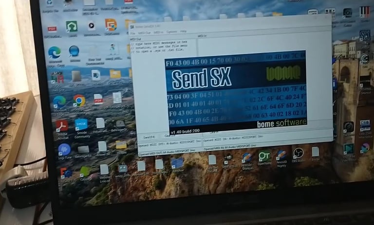
Some software to transfer SYSEX files. I used Bome SendSX https://www.bome.com/products/sendsx but you could use MIDIOX as well.
You will also need some DX7 patch files in SYSEX format. There are a lot available online. Bear in mind that the new synth will only load the first ten patches from the file.
Also, before you try to transfer anything to the synth, you will have to set it up to allow it to receive SYSEX messages. this is done as follows.
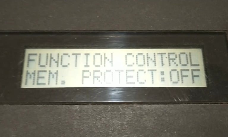
Press FUNCTION + Key 20 (Memory Protect)
Press The NO/OFF/-1 button to disable memory protect.
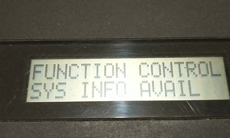
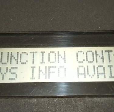
Press FUNCTION + Key 6 repeatedly until the screen shows SYS INFO UNAVAIL
Press the YES/ON/+1 key to show SYS INFO AVAIL
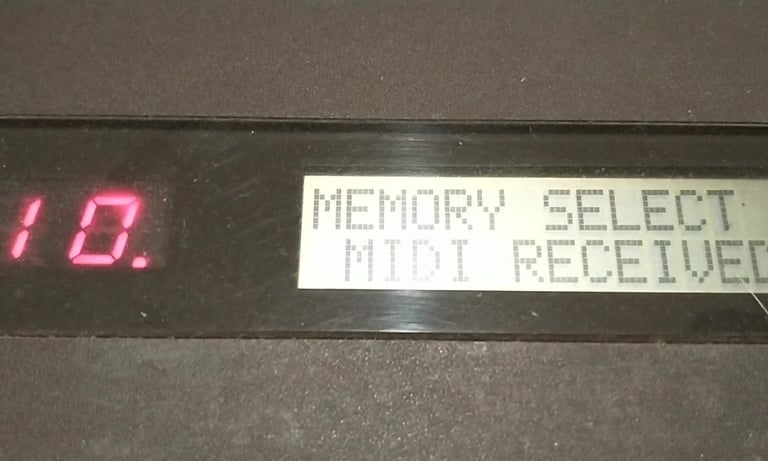
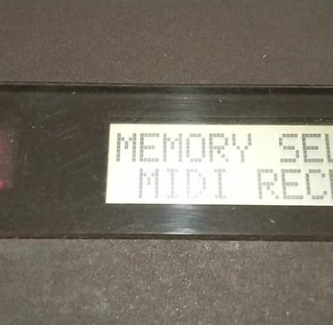
After carrying out the above, you should be able to send the patches to the synth. Note the synth only responds with 'Received' at the end of a transfer.
Conclusion and Video
After all of this the synth seemed to work very well. It was pretty easy to transfer the patches via MIDI as well.
I also tried it out with the Edisyn synth editor (https://github.com/eclab/edisyn) using the DX7 option, and this worked without problems (so far). I'm hoping It will allow easy access to the operators that cant be accessed from the DX9 front panel.
I've uploaded a video of the process to YouTube. Please Watch / Like / Subscribe and Support if you can. Thank you.
I'll try do do some more proper sound demos and editing using Edisyn, when I get the chance.

Help me proceed with anything on this site.
If you like what I'm doing, please feel free to support me and keep this site alive.