
TB303_SPICE
Simulations of a Roland TB303 oscillator.
Some initial simulations of a Roland TB303 oscillator in LTSPICE
I wanted to try out some SPICE circuit simulations for various synthesizer circuits. So initially I tried to simulate a Roland TB303 VCO circuit (Voltage Controlled Oscillator). I used the free LTSPICE simulator (Now available from Analog Devices). The main focus was towards the simulation of the oscillator core, at the component level. Later on, behavioural blocks were used to add filtering and rudimentary envelopes. In the future, the plan is to simulate these other blocks at the component level. Also in the future, I plan to do some more simulations of synth circuits. The main motivation for this, is that I sometimes use SPICE simulations to evaluate circuits, before and during physical prototyping.
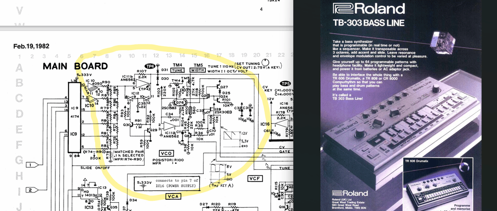
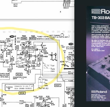
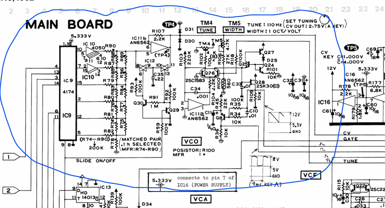
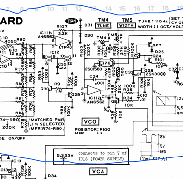
So initially I managed to obtain a copy of the the TB303 service manual online. The key page showing the oscillator schematic is shown below.
After looking at the schematic, it was then transferred into the LTSPICE simulator
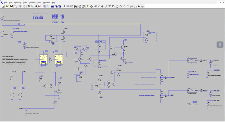
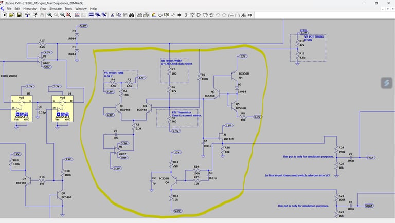
The main part of the VCO is shown below.
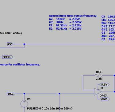
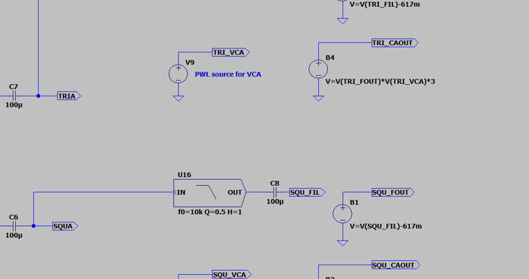
The inputs for the control voltage of the oscillator are shown below. These could be changed from fixed voltages to variable voltages. Initially, fixed voltages were used to roughly set voltages that corresponded to desired output frequencies (or notes). Later on the fixed voltages were changed to piecewise-linear sources, that allowed voltages to be generated from tables in a time versus voltage form.
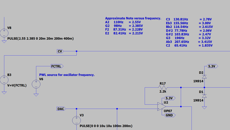
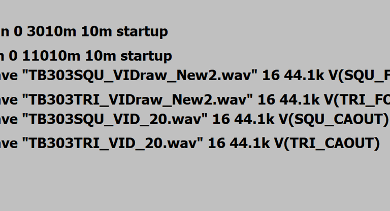
LTSPICE also allows the results from simulations to be exported to a *.wav file. These files could then be imported into Audacity for further post processing and playing.
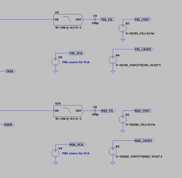
The main outputs from the component level oscillator were fed into behavioural filters and simple behavioural envelope generators (like a voltage controlled amplifier). The envelope generators could have the envelopes changed over time. This was achieved by using a piecewise-linear source with a table of voltage versus time values. The output circuits are shown below.
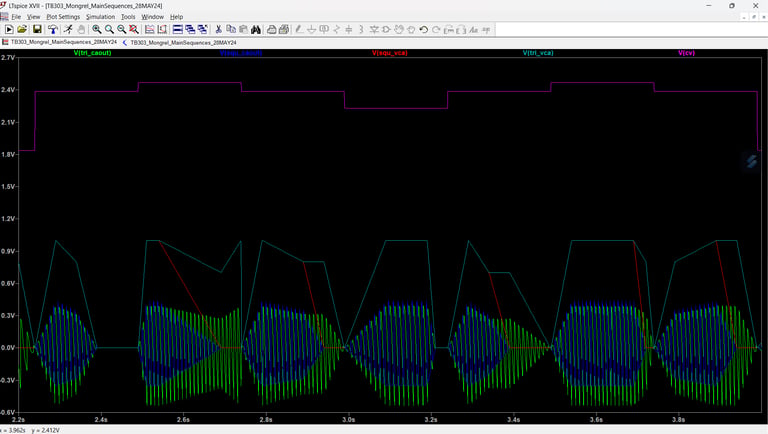
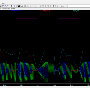
Various simulations were carried out. The waveforms were exported to Audacity to check the audio output, and also experiment with further post processing. The image below shows some of the outputs from a sequenced simulation. The top line shows the VCO control voltage. The pale-blue line shows the triangle envelope control voltage. The red line shows the square envelope control voltage. Finally the oscillator output waveforms are shown in blue and green at the bottom of the plot.
An initial video of the simulations, and the outputs being played in Audacity, has been uploaded to YouTube. The link is below. When I get the chance, I will try to do some simulations of other circuits.

Help me proceed with anything on this site.
If you like what I'm doing, please feel free to support me and keep this site alive.