
Stylophone Beat Sync Output Mod
Modifying a Stylophone Beat so that it has a sync output to connect to other gear. Includes link to YouTube demo video.
Modifying a Stylophone Beat to have a sync clock output.
I got a Stylophone Beat for a present a while ago. I've been meaning to add some sort of clock sync output to it so that I can connect it to some of my other gear. Initially, I was going to try to do a wholly external modification with a photo transistor circuit placed on the click LED, however it looked easier to open the case and connect directly to the circuit board somewhere.
The first stage was to open the case by removing the four Torx screws. Be careful when you lift the case as both half's are connected together via a cable. Lift the half slowly and try and disconnect the cable from the bottom half of the case. Note, the main board may lift, but make sure that the clear LED cover and the switch plastics are aligned correctly on re-assembly.
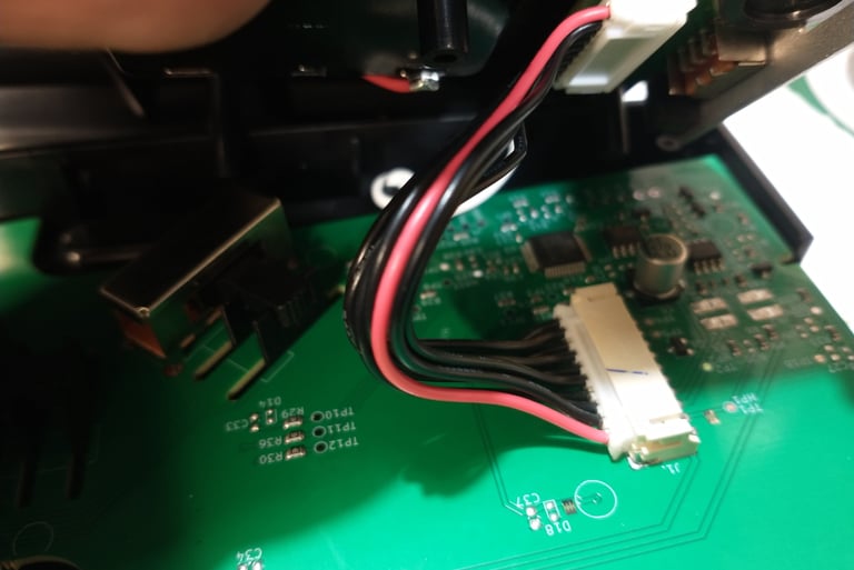
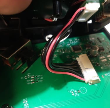
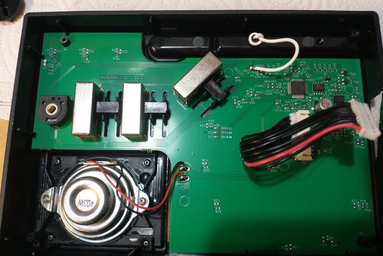
After separating the two half's of the case, the next stage involved identifying connection points and adding suitable wires. The picture below show the click LED and its bias resistors in the top left-hand corner. As the click LED flashes in accordance to the tempo, this seemed to be a logical place to provide a sync signal. Scoping out the right hand side of the bias resistors revealed that they did provide a suitable sync signal. The signal was a pulse train with an approximately 4V peak level. The signal should be fine for connecting to sync inputs on other gear, but double check first.
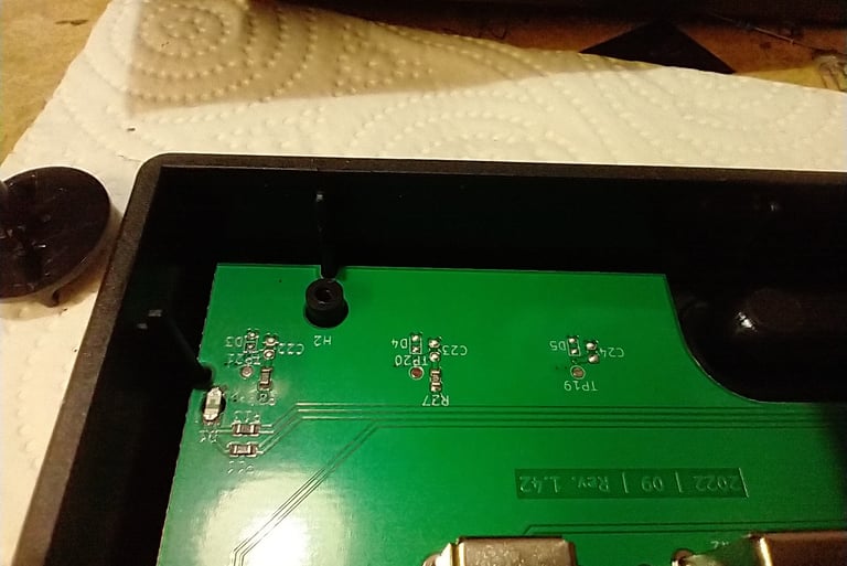
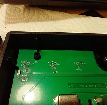
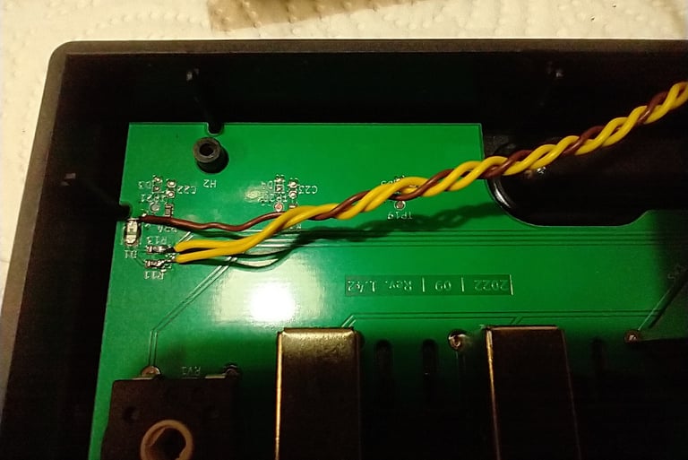
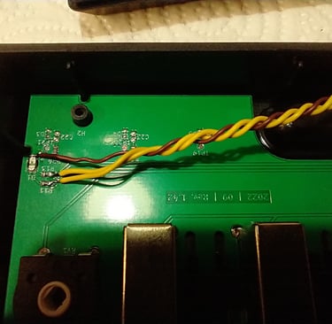
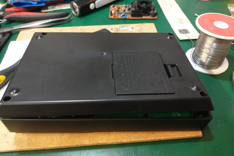
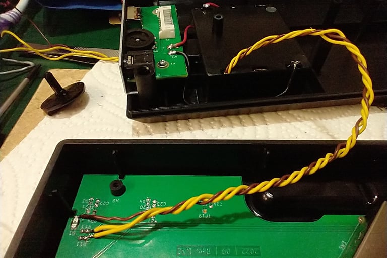
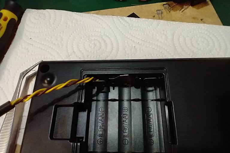
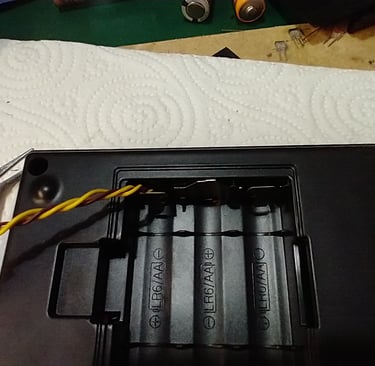
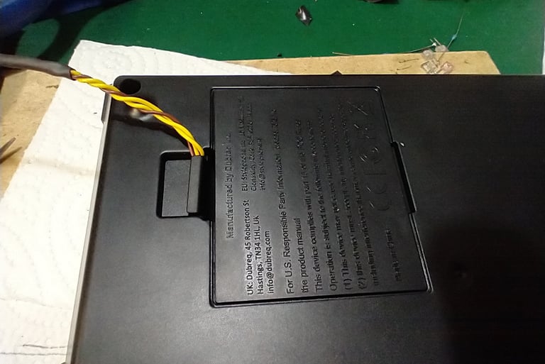
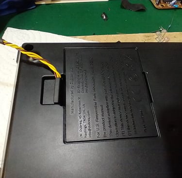
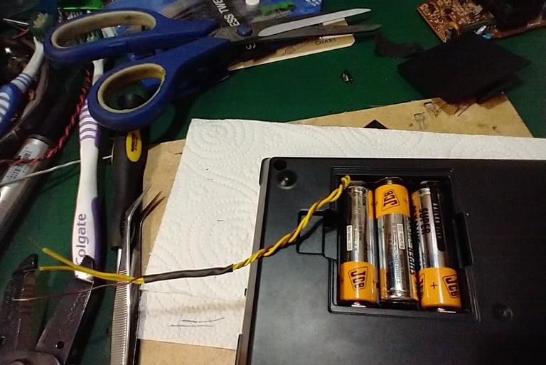
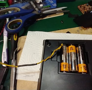
The right hand picture above, shows the wires connected to the LED bias resistors and LED. The two yellow wires are for the clock signals (you may only need one -see below) and the brown on is for the ground connection. Try to use thin wires of an appropriate length, as then they can be routed through a slot in the battery compartment, as shown in the pictures below. When the Beat is re-assembled you should also be able to carefully close the battery lid. Note: I used two wires as I forgot to check if one would work when the Beat was in both record and play mode - it seems that one would have done, if I'd have checked ! I cant remember which one though, you should be able to find out through simple trial and error.
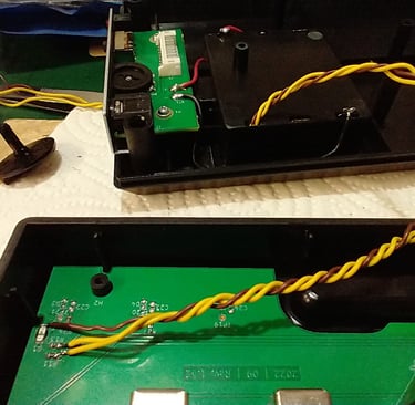
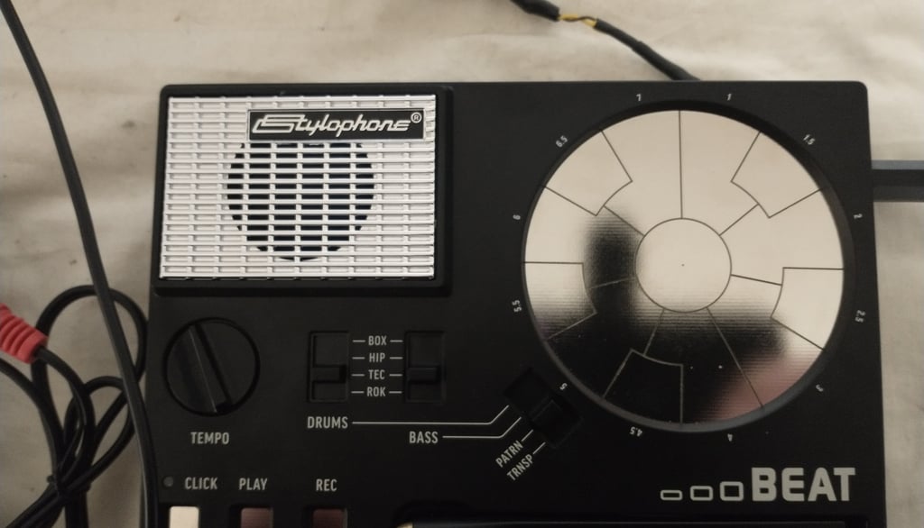
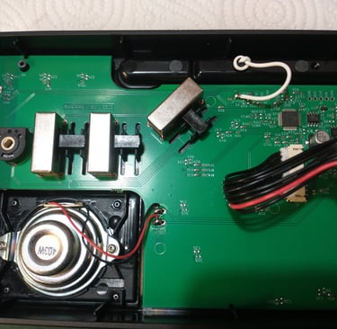
A final note: Take care when replacing the back of the Beat. Make sure all of the boards and switch plastics are aligned and that you have not missed out the clear plastic led cover. The switch plastics are visible on the three switches (large rectangular silver items) in the following picture.
I have uploaded a video to YouTube that outlines the procedure (same as this really), but also adds some sound demos. Please watch, like and subscribe if you get the chance. Thanks, Martin.

Help me proceed with anything on this site.
If you like what I'm doing, please feel free to support me and keep this site alive.