
Dead Bug Synthesizer part 1
Building an exponential VCO for a synthesizer using simulations, breadboarding and 'Deadbug' prototyping techniques.
I recently wanted to start building some synthesizer prototypes again, using techniques I haven't used for a while. For a long time my workflow for electronic design has been, calculate, simulate and then straight to PCB manufacture with a fabrication service. I do have prototype capabilities as well, for PCB's, including photo etching and CNC. However, I really wanted to go back in time and do some builds with prototyping techniques I started out with (and generally didn't like much). I even wanted to try and avoid Veroboard and go back to "Deadbug" techniques (IC components are upside down and look like Dead Bugs). It's generally a not very pretty technique (especially in this case), but it does work for relatively simple circuits. Note: I used to use it for very simple RF prototyping a long time ago.
Anyway, this blog shows some pictures of a dead bug build for an exponential VCO. There are also some video links at the end that include some sounds and mini jams. The build was OK and the oscillator worked OK, but does still require some tuning and adjustments. I did the final testing using the CV output from an Arturia Keystep37. I think the oscillator will be of use connected to some other modular gear, but I'm probably not going to take the Analogue VCO any further, and will most likely opt for a digital micro based oscillator, used in conjunction with analogue filters. However I am planning on doing some more simulations, builds and associated videos for other synthesizer blocks, for example, filters, envelope generators, wavefolders, waveshapers, etc.
If you like any of this, please like and subscribe to my YouTube channel as well. It includes lots of patch ideas for various synths and accompanying sound demos.
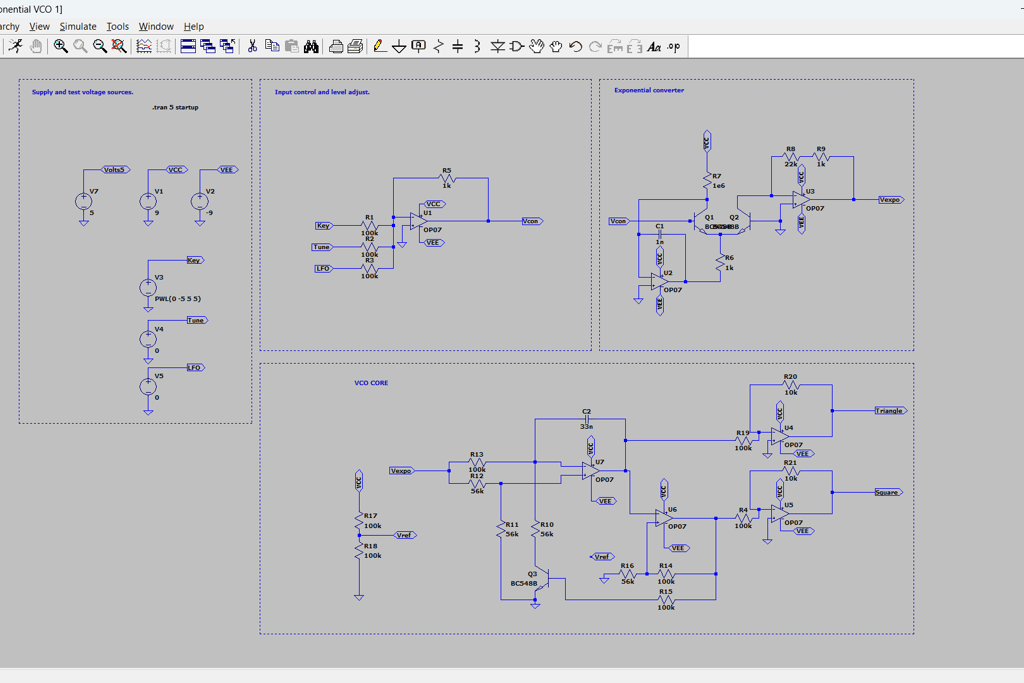
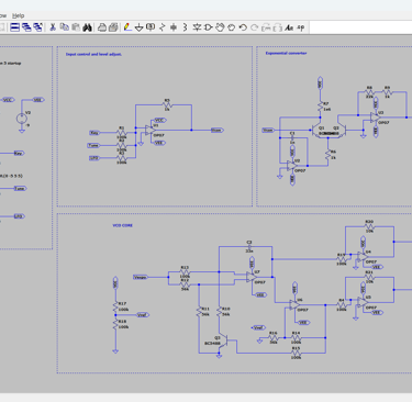
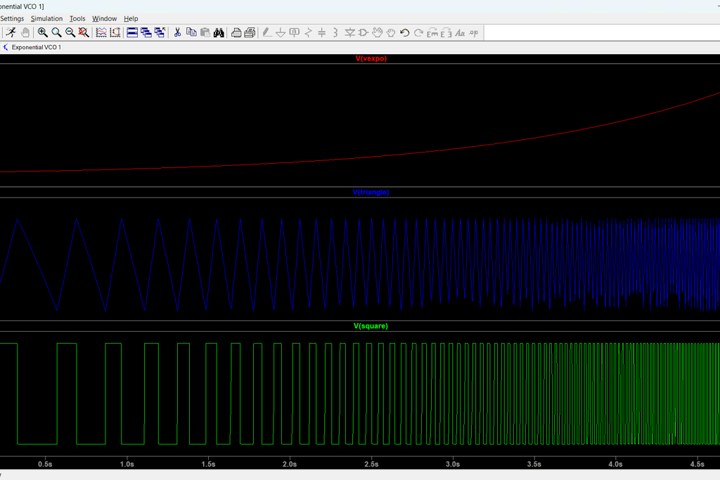
The basic schematic in LTSPICE along with some simulation results are shown below.
Note: component values may have changed in the final build, but it should give you a starting point.
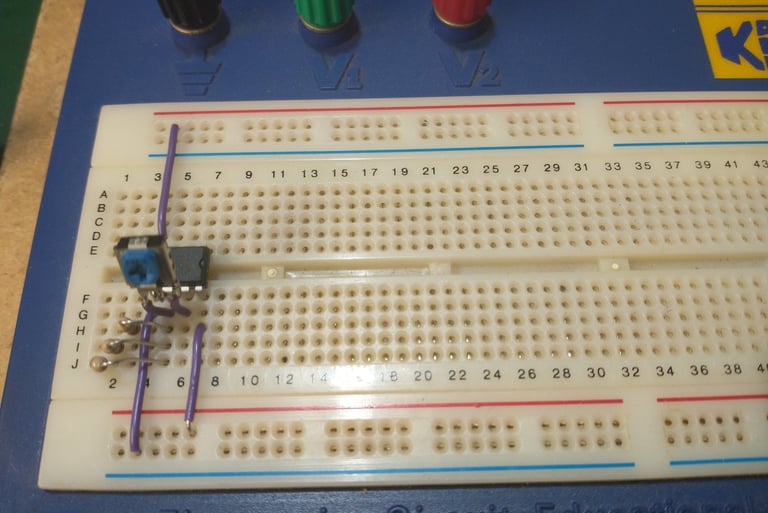
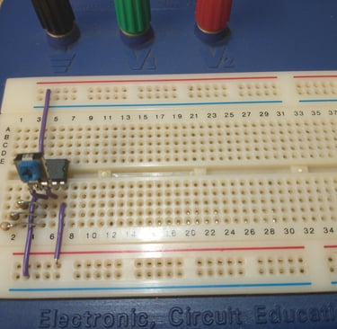
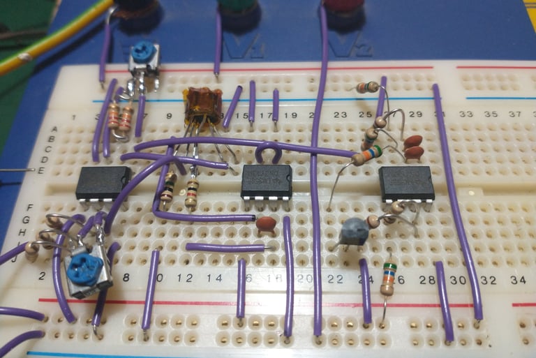
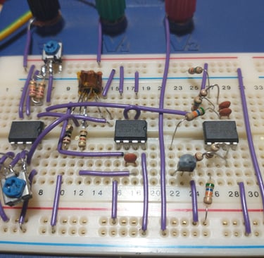
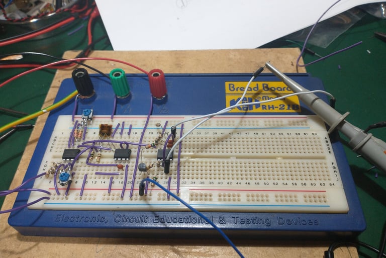
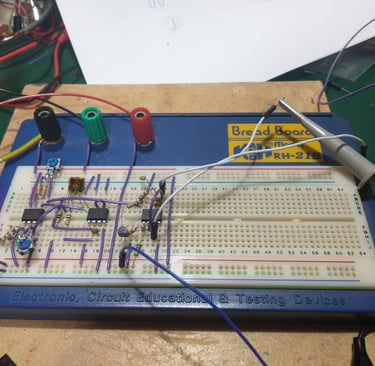
Prototyping using a breadboard
Input stage
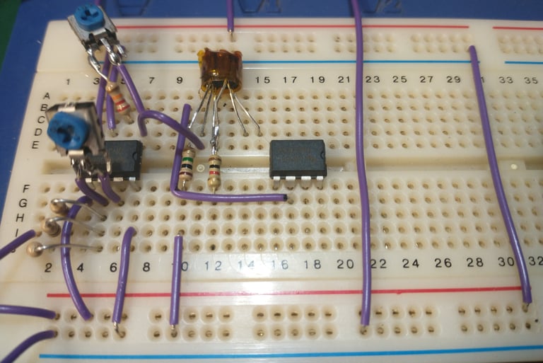
Adding exponential converter
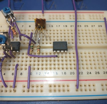
Adding the oscillator
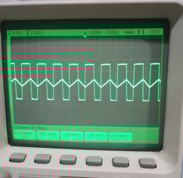
Checking the outputs
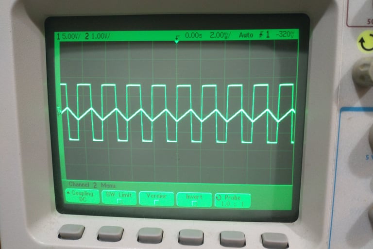
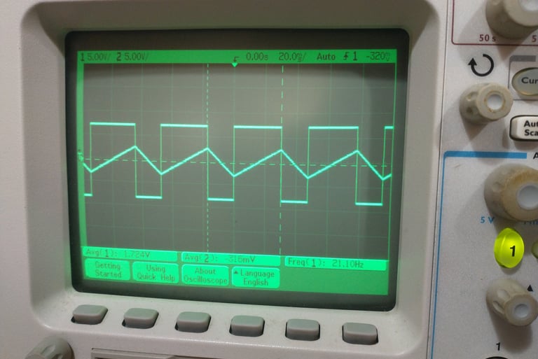
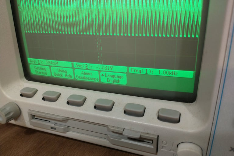
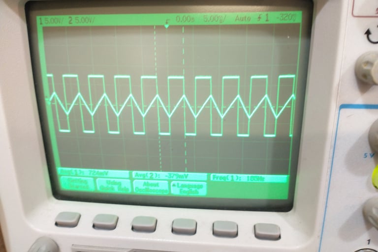
Oscilloscope outputs 1
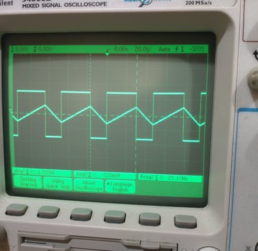
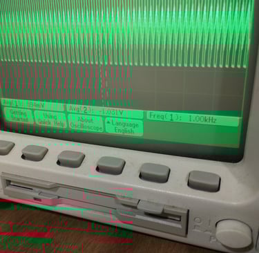
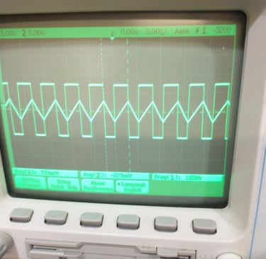
Oscilloscope outputs 2
Dead Bug prototype build
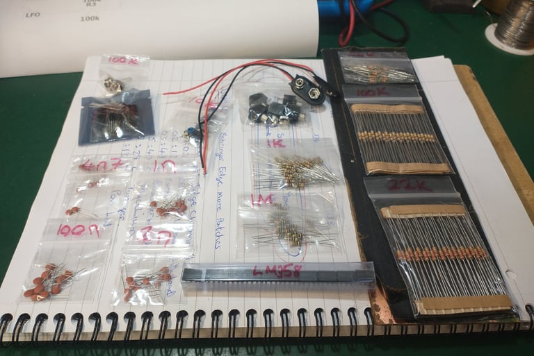
Components
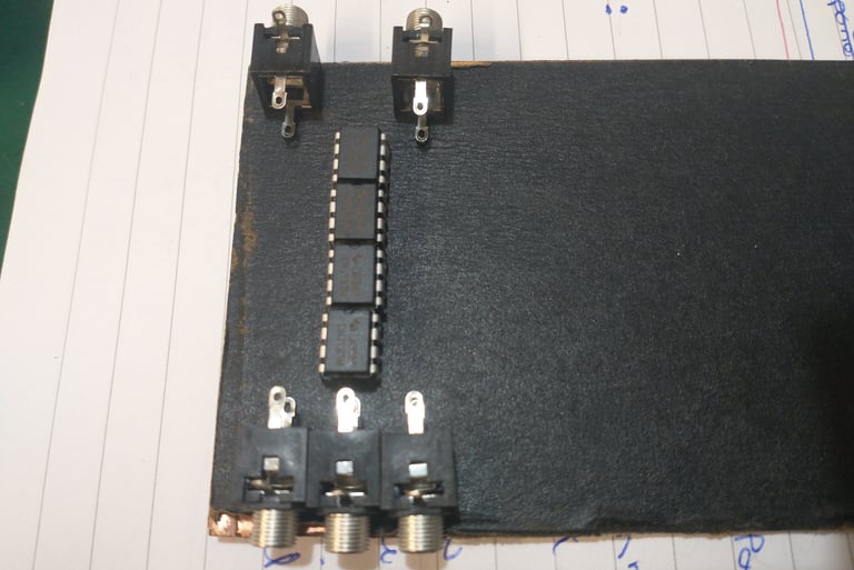
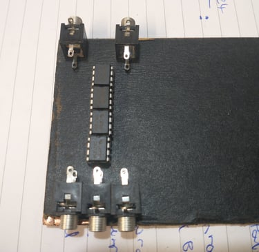
Floor planning
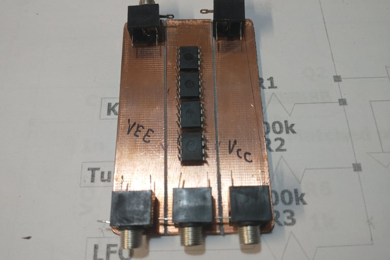
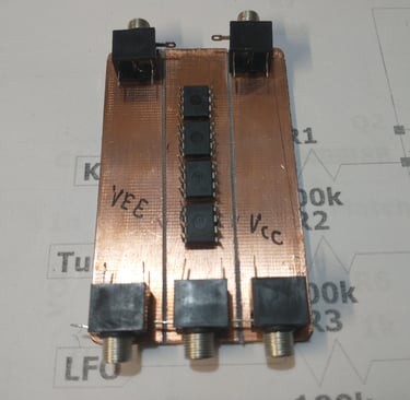
PCB with VCC, VEE and GND cuts
Anchoring ICs using power connections.
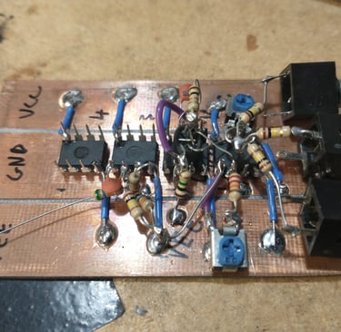
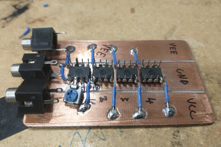
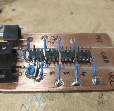
Deadbug VCO build stage 1
Deadbug VCO build stage 2
Deadbug VCO build stage 3
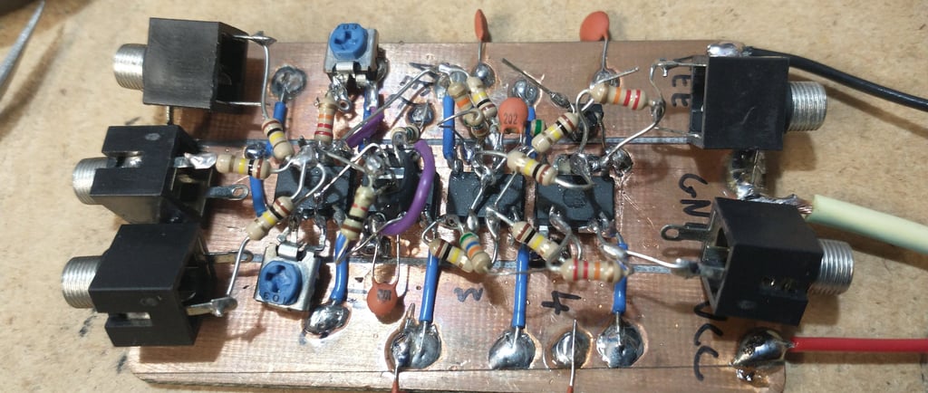
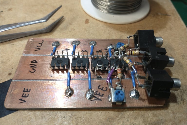
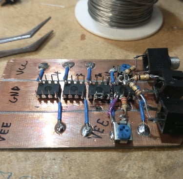
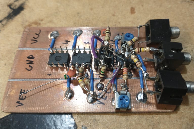
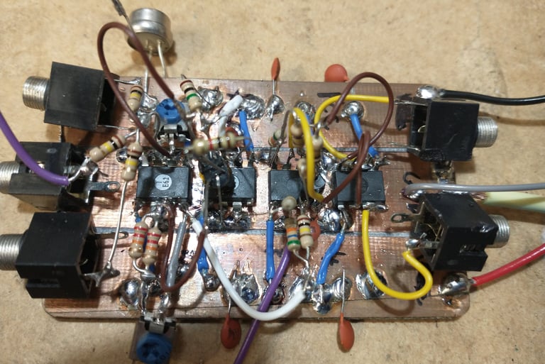
Deadbug VCO final build
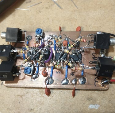
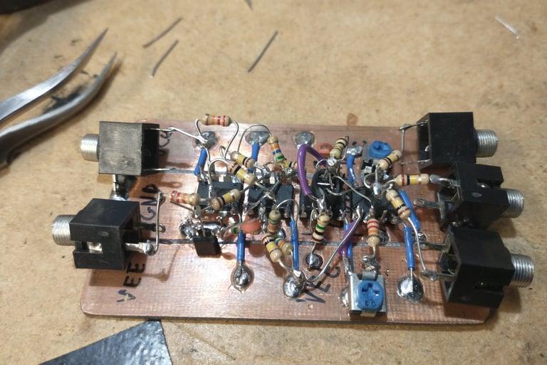
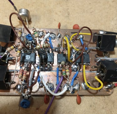
Deadbug VCO testing 1
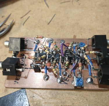
Deadbug VCO testing 2
Some videos of the build process for the Deadbug VCO, along with some demo sounds, are linked below. Some test sound demos for the Deadbug VCO used an Arturia Keystep37 to sequence the VCO, and used a Roland MC-505 for the drum parts. Please like and subscribe if you can, Thanks.


Help me proceed with anything on this site.
If you like what I'm doing, please feel free to support me and keep this site alive.